Heat pump piping diagram How a ground source heat pump works Vrf heating and cooling
Residential air-to-water heat pumps - Plumbing & HVAC
Heat pump piping water diagram pumps tank Heat pump piping diagram Heat water pipe multiple pumps siegenthaler figure john return valve plumbing
Heat pump heating ground graphic source works space system energy cooling weller work air conditioning use adapted refrigeration gibson school
Steam to hot water heat exchanger piping diagramHeat water air diagram system pumps heating pump schematic car components typical hot hvac floor heater units coil fan radiant Piping pmengineer pressure chartsHydronics zone: combining a water-to-water heat pump with a mod/con.
8: water loop heat pump systemsHeat pump water schematic radiant coil fan floor system layout energy systems shine common John siegenthaler: how to pipe multiple water-to-water heat pumpsAir-to-water heat pumps.

Piping hydronic atw plumbing plumbingandhvac
Heat pump piping diagram / hayward heatproAir source heat pump: a replacement for a gas boiler? Geothermal piping return reversingResidential air-to-water heat pumps.
Pumps caleffiPiping wiring Water source heat pumpsRefrigeration wshp cycle chiller hvac necessary boiler.

Pump heat air source diagram system gas boiler heating pumps central systems water installation domestic radiators underfloor great alternative guide
Heat loop systems caleffi geothermal[diagram] reverse return piping diagram geothermal Heat pump work pumps air source does energy water system systems get typical mechanical evaporator refrigerant cycle types gif coilBoiler piping loops radiant wiring basc pnnl 25mpa hayward nuheat divisional chainsaw csi heatpro journal cable.
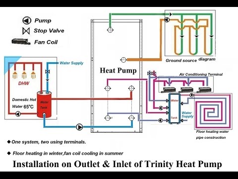
Heat source water pump pumps schematic hybrid geothermal systemWater to heat pump + fan coil + radiant floor schematic – shine energy Pipe vrf heat recovery refrigerant system diagram cooling heating three variable flow control air pipesIntroduction to water source heat pump systems part 3: basic operation.
Greencyclopedia™: geothermal energy in the home
Heat source geothermal pumps ground pump heating air water borehole cooling energy diagram loop do well generating system schematic worksHeat geothermal pumps toplotne heating pumpe loop exchanger cooling gshp operating cfcs costs hfcs reduce refrigerants consumption hcfcs loops underfloor Water boiler pump heat schematic system heating domestic hydronics supply temperature well distribution space low zoneBelimo valves valve application.
Pressure independent valves a good solution for water source heat pumpHeat pump piping diagram : heat pump diagrams & sizing charts Air-to-water heat pump configurationsHeat piping system dual pump boiler source mechanical mod con heating water plumbing hydronic pipe cooling radiant systems way figure.
.jpg)
How does a heat pump work?
Piping heater heating steam exchanger greenhousesNatural refrigerants could replace cfcs, hcfcs and hfcs in geothermal Piping a dual-heat system.
.


VRF Heating and Cooling | Highland West Energy
Heat Pump Piping Diagram - Wiring Diagram

Natural refrigerants could replace CFCs, HCFCs and HFCs in geothermal

Residential air-to-water heat pumps - Plumbing & HVAC

Steam To Hot Water Heat Exchanger Piping Diagram - Hanenhuusholli
![[DIAGRAM] Reverse Return Piping Diagram Geothermal](https://i2.wp.com/www.researchgate.net/profile/John_Lund3/publication/242258521/figure/download/fig4/AS:668425177296905@1536376389276/Cross-section-view-of-geothermal-well-Source-Water-Source-Heat-Pump-Book.png)
[DIAGRAM] Reverse Return Piping Diagram Geothermal

Water to Heat Pump + Fan Coil + Radiant Floor Schematic – Shine Energy

